Dolphin Centrifuge provides this illustrated glossary of 20 disc centrifuge bowl parts and 14 industry-specific terms. Covering components like the disc stack, gravity disc, and sliding piston operating at 4,000-10,000 RPM, this guide serves technicians maintaining Alfa Laval disc stack centrifuges. Based in Warren, Michigan, Dolphin Centrifuge stocks replacement parts for all major models.
Synopsis
Disc centrifuges are a unique set of machinery that has its own parts and related vocabulary. There are specific terms used when referring to disc centrifuges, which are uncommon in the broader industrial machinery world. Engineers, technicians, and operators new to this equipment frequently encounter unfamiliar terminology that is not found in general mechanical engineering references.
We have categorized these terms into two subcategories. The first section explains parts specific to disc centrifuges, and the second section explains terms unique to disc centrifuges. Each entry includes a description of the component's function, its relationship to other parts, and maintenance considerations where applicable.
This first section elaborates on the unique centrifuge parts common to Alfa Laval disc centrifuges. We describe the specific component's function and illustrate it within the exploded view of the assembly or a photograph. This explanation will help the reader understand the part in detail and recognize it in the field during maintenance, repair, or troubleshooting.
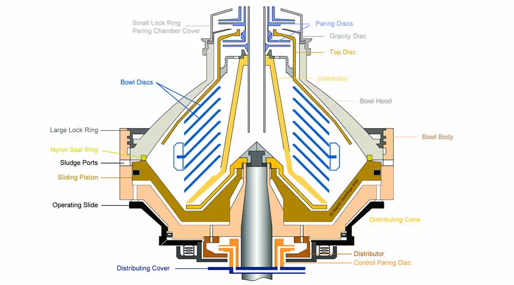
The featured image on the top of the page is an Alfa Laval disc stack centrifuge bowl cross-section showing the parts' location within the centrifuge bowl. This cross-sectional view is one of the most valuable reference diagrams available for understanding how all of the individual bowl components fit together and interact during operation.
Understanding the function of each component is essential not just for ordering replacement parts, but for diagnosing operational problems, performing preventive maintenance, and communicating accurately with service technicians. A technician who understands the role of the nylon seal ring, for instance, will immediately understand why a bowl leak and a worn sliding piston lip are connected problems — and will prioritize replacing the inexpensive consumable part before the expensive non-replaceable one is damaged.
This list is alphabetically organized.
Disc Centrifuge Bowl Parts — Quick Reference
The following table summarizes all 20 disc centrifuge bowl parts covered in this glossary, along with their alternate names and primary function. Use this table as a quick reference when identifying parts in the field or when communicating with parts suppliers and service technicians.
| Part Name | Alternate Names | Primary Function | Replaceable? |
|---|---|---|---|
| Bowl Disc | Disk, conical plate, plate-stack, disc-stack | Increases settling surface area; heart of the centrifuge | Yes |
| Bowl Body | Bowl drum, bowl shell | Outer rotating housing for all bowl assembly components | Yes (major repair) |
| Bowl Hood | Bowl top | Upper cover that completes the bowl outer envelope | Yes |
| Bowl Liner | Piston liner | Protects sliding piston from abrasive wear | Yes (consumable) |
| Bowl Spindle | — | Vertical transmission shaft; transmits rotation to bowl | Yes (precision part) |
| Control Paring Disc | — | Transfers operating water from stationary frame to rotating bowl | Yes |
| Distributing Cone | — | Smoothly distributes incoming fluid below the distributor | Yes |
| Distributing Cover | — | Conduit for operating water; mounts control paring disc | Yes |
| Distributing Ring | Water ring | Rotating water transfer mechanism; receives jet from control paring disc | Yes |
| Distributor | Disc carrier, disc tower | Mounts and aligns all discs in the disc stack | Yes |
| Gravity Disc | Gravity ring | Controls liquid-liquid interface position within bowl | Yes (sized per application) |
| Large Lock Ring | — | Locks bowl hood to bowl body; compresses bowl assembly | Yes |
| Nylon Seal Ring | Bowl seal ring | Primary bowl seal; protects sliding piston lip from wear | Yes (consumable — replace regularly) |
| Operating Slide | — | Opens/closes water chamber; triggers sludge ejection cycle | Yes |
| Paring Disc | Paring disc pump, centripetal pump | Static centripetal pump; converts bowl rotation into outlet pressure | Yes |
| Port Liner | Port wear clips | Sacrificial steel clips protecting sludge ports from abrasive wear | Yes (consumable) |
| Sliding Piston | Sliding bowl bottom | Moving component that opens sludge ports for ejection cycle | Expensive; protect with nylon seal ring |
| Sludge Ports | Sludge ejection ports | Rectangular slots allowing solids to exit bowl during ejection | Part of bowl body; protect with port liners |
| Small Lock Ring | Paring chamber cover | Secures gravity disc; houses heavy-phase paring chamber | Yes |
| Top Disc | — | Dome-shaped cover funneling light phase to center outlet | Yes |
Disc Centrifuge Parts Glossary
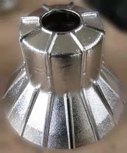
Bowl Disc
aka disk, conical plate, plate-stack, disc-stack
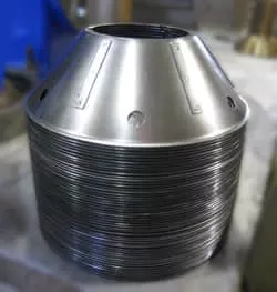
A bowl disc is a conical-shaped plate inside the rotating bowl assembly of the disc centrifuge. A stack of these discs is the heart of disc-type industrial centrifuges.
The purpose of these discs is to increase the surface area of settling available to the rotating fluids inside the bowl. This added surface area increases the efficiency of the centrifuge multi-fold. In other words, the discs reduce the settling distance of the process liquid. The photo shows a complete disc stack from an Alfa Laval centrifuge bowl.
The inter-disc spacing is maintained using caulks (or ribs), which are thin strips of steel welded to the discs' surface. These caulks are radially oriented and uniformly spaced around each bowl disc surface. The radial orientation of the caulks allows the flow of the process fluid in the same direction.
There are evenly spaced and matching holes on all the discs in a stack. These holes form a channel allowing upward movement of the process fluid through the disc stack. Depending on the centrifuge, these holes are closer to the outer periphery of the inner edge of the discs.
Another variation between discs is the caulk thickness, which varies the inter-disc spacing. For thicker or more viscous fluids, the caulks are thinner. This implies that the discs are closer to each other. The caulks are thicker for less viscous fluids (like water), allowing a wider gap between the discs.
The number of discs in a stack varies by centrifuge model and application. A larger stack means more separation surface area and typically higher throughput capacity. Bowl discs are precision-stamped from stainless steel and must be free of warping, deformation, or scale buildup to maintain proper separation performance. When reassembling a bowl, the discs must be re-stacked in the correct orientation with the caulks aligned to maintain the designed flow path through the stack.
Bowl Body
aka Bowl Drum, Bowl Shell
The bowl of a disc centrifuge is the outer, rotating body that houses all the bowl assembly components. Bowl bodies rotate upwards of 5000 RPM up to 15,000 RPM.
Depending on the type of centrifuge, the bowl body may have slots around the periphery in the 'self-cleaning' centrifuges. These slots or ports are openings for the sludge to exit the bowl during the sludge ejection process. These sludge discharge ports can wear out based on the type of solids, especially in the case of abrasive particles.
Manual clean centrifuges have a solids bowl body without any slots or ports.
The bowl body is precision-machined from high-grade stainless steel or duplex steel to withstand the extreme centrifugal stress during operation. The bowl body must be periodically inspected for erosion, cracks, or corrosion, particularly around the sludge port openings. Any compromise in the structural integrity of the bowl body is a serious safety concern at the operating speeds of these machines. The internal water passages within the bowl body are also subject to scale buildup from hard water and should be cleaned during each scheduled overhaul.
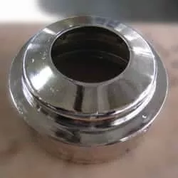
Bowl Hood
aka Bowl Top
The bowl hood is the upper cover on the centrifuge bowl body. Once assembled with the bowl body, this forms the complete outer envelope of the rotating bowl assembly. The bowl body is assembled on the upper end of the bowl spindle.
The large lock ring integrates the bowl hood into the bowl body.
The bowl hood houses several critical components including the gravity disc seat, the nylon seal ring groove, and the upper passages for the separated liquid phases. In a three-phase (liquid-liquid-solid) centrifuge, the bowl hood contains both the light-phase and heavy-phase exit passages. The hood must be inspected during overhaul for wear at the seal ring groove, as an eroded groove will not retain the nylon seal ring correctly, leading to bowl leaks during operation. The threads on the bowl hood that mate with the large lock ring are also a critical area — any damage here can make proper bowl assembly impossible.
Bowl Liner
aka Piston Liner
The sliding piston is one of two moving parts within the bowl. This part is discussed in a subsequent section below. The process fluid flows along the upper surface of this part.
The bowl liner is a thin, steel part that is installed on top of the sliding piston within the disc centrifuge bowl. This liner protects the piston from wear, which can occur when the process fluid carries abrasive solids.
The bowl liner is a sacrificial wear part that is far less expensive than the sliding piston it protects. By absorbing the abrasive wear from the process fluid, the bowl liner extends the service life of the sliding piston significantly. When abrasive solids are present in the process fluid — such as sand, metal fines, catalyst particles, or hard mineral solids — the bowl liner should be inspected at every major service interval and replaced before it wears through. If the liner wears completely, the abrasive damage extends to the sliding piston itself, which is a much more costly part to replace. In applications with high solids loading, the bowl liner may need replacement during each overhaul cycle rather than only when visibly worn.
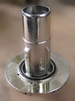
Bowl Spindle
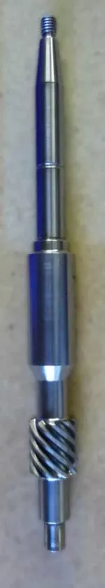
The bowl spindle is the vertical transmission shaft of the disc centrifuge. It transmits the rotation from the gear train to the bowl assembly. The centrifuge bowl body is assembled on top of the bowl spindle.
The upper part of the bowl spindle has a precise taper section with a corresponding tapered hole in the bowl body. These tapers have to be precisely ground to match each other. Mating these two conical parts ensures complete surface contact between the bowl spindle and the bowl body. The friction between these components transmits the rotation from the spindle to the bowl assembly.
Therefore the bowl and spindle tapers need to match precisely for the smooth operation of the centrifuge. Any mismatch between the conical surfaces leads to the bowl mass being off-center from the rotating axis. At the operating speed of the bowl, this can cause imbalance and lead to excessive centrifuge vibrations.
Precision machined surfaces in the middle section of the bowl spindle for mounting the bearings.
The lower part of the bowl spindle has a worm gear mounted on it. In some smaller centrifuges, this gear is integral to the bowl spindle.
Bowl spindle runout is an essential checkpoint during disc centrifuge repair. Minor deviations in the spindle's straightness can occur over time, leading to a slight runout at the top of the shaft. The loss of concentricity leads to excessive centrifuge vibrations due to the rotating bowl mass being off-center. During overhaul, the spindle taper surface must be cleaned and inspected for fretting, corrosion, or mechanical damage. The taper surfaces of both the spindle and the bowl body should be lapped together periodically to ensure a precise fit. Any visible step, scoring, or galling on the taper surface is cause for replacement of the spindle or bowl body, as the imprecise contact will transfer to bowl vibration at operating speed.
Control Paring Disc
The control paring disc is part of the operating water system of 'self-cleaning' centrifuges. It is a non-rotating part that functions as a water-conveying device. It transfers water from the stationary frame of the centrifuge to the rotating bowl assembly.
In a fully assembled centrifuge, the control paring disc is stationary and positioned within the underside of the rotating bowl body. It discharges the water in the form of a jet that enters the open cavity inside the rotating distributing ring (explained below). This mechanism allows the transfer of the operating water between the stationary and rotating parts of the bowl.
The precise alignment of the control paring disc jet with the opening of the distributing ring is critical. If the control paring disc is bent, clogged, or misaligned, the water transfer to the rotating bowl will be incomplete or imprecise, causing unreliable bowl opening and closing during the sludge ejection cycle. During every overhaul, the control paring disc should be inspected for blockage in its water passage and verified to be straight and undamaged. Even a minor bend can cause the water jet to miss the distributing ring opening, resulting in operational failures.
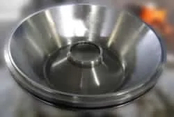
Distributing Cone
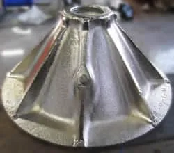
The distributing cone is part of the rotating bowl assembly. It is located within the bowl body above the sliding piston (described below).
The distributing cone distributes the incoming fluid smoothly within the underside of the distributor. The distributor is described in detail in the following section.
The geometry of the distributing cone is designed to redirect the incoming process fluid from an axial (downward) flow to a radial outward flow that can enter the disc stack through the holes in the distributor. This smooth redirection is important because turbulent introduction of the process fluid into the disc stack can disrupt the settled layers and degrade separation efficiency. Abrasive particles in the process fluid can erode the surface of the distributing cone over time. When significant erosion is observed, replacement is recommended to maintain proper flow distribution within the bowl.
Distributing Cover
A distributing cover is another component of the operating water system attached to the centrifuge frame underneath the bowl body. The bowl spindle passes through the distributing cover. The control paring disc (detailed above) mounts on the distributing cover.
This component 'covers' the frame opening below it — that's why the 'cover' is in its name. It is a conduit for the operating water and carries the water to the control paring disc. There are intricate passages within the distributing cover for water to flow through.
The internal passages can get clogged with sludge and mineral deposits from the water over time. Keeping the distributing cover clean from the inside is critical to ensure the centrifuge's trouble-free operation.
This is a critical part of the operating water system of the centrifuge. The functional aspect of this part is explained in our Bowl Troubleshooting article. During maintenance, the distributing cover should be removed and flushed thoroughly. In areas with hard water supply, scale buildup inside the cover passages is a common problem and can restrict the water flow needed for reliable bowl operation. Chemical descaling or mechanical cleaning of the passages is recommended at each scheduled overhaul.
Distributing Ring
aka Water Ring
The distributing ring is a rotating component that is a part of the centrifuge's operating water system. As referenced in the control paring disc section above, the distributing ring corresponds to the water transfer mechanism.
This part nestles within the bottom section of the rotating bowl body. It is fastened to the bowl body by bolts from within the bowl.
The jet of water from the control paring disc enters a precisely located opening on the inner diameter of the distributing ring. The centrifugal force radiates this water outwards into the water passage within the bowl body.
This is also a critical part of the operating water system of the centrifuge. The functional aspect of this part is explained in our Bowl Troubleshooting article. The small opening on the inner diameter of the distributing ring that receives the water jet from the control paring disc must remain clean and unobstructed. Mineral scale or sludge deposits can partially or fully block this opening, causing unreliable or absent bowl operation. This opening should be checked and cleared during every bowl service.
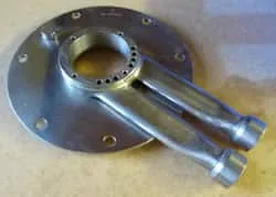
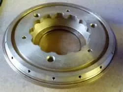
Distributor
aka Disc Carrier, Disc Tower
As the alternate name 'disc carrier' implies, the centrifuge distributor has mounted all the discs (stack). The distributor is the fixture for the conical plates within the centrifuge bowl. It aligns the cones correctly using an alignment key and corresponding slots on all discs.
The process fluid flows through the center of the distributor towards the distributing cone below it. The distributor has holes that line up with the holes in the discs. The process fluid passes through these holes into the disc stack.
The distributor features radial ribs around its core, which creates a gap between the discs' inner edge and the center of the distributor. The separated liquid flows through this gap upwards towards the bowl top.
The alignment key embedded in the distributor is a critical component. The distributor wears due to the constant flow of fluid with sludge along its surface. This wear can cause the discs to fit loosely around the ribs of the distributor.
Excessive wear can allow the discs to rotate about the distributor. This misalignment causes the holes on the distributor to not line up with those in the discs. The fluids can no longer flow in the designed passages leading to the malfunction of the centrifuge. During each overhaul, the distributor ribs and alignment key areas should be carefully inspected for wear. If the discs show any looseness or side play around the distributor ribs, the distributor must be replaced to restore correct disc alignment and flow distribution.
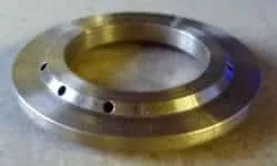
Gravity Disc
aka Gravity Ring
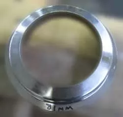
The gravity disc is a stamped steel part on top of the disc centrifuge bowl hood. The gravity disc has a controlled inside diameter hole, which controls the position of the interface between the two liquid phases in the case of a liquid-liquid separation centrifuge.
This interface is critical for the operation of the centrifuge. If the interface is too far radially outward (large gravity ring hole size), there is not enough heavy phase liquid in the bowl.
The inner oil column's hydrostatic pressure pushes out the water phase and exits the bowl through the heavy phase outlet. This condition is undesirable, as the lighter fluid (usually oil) is now exiting the bowl through the incorrect outlet. This is the 'break-over' condition discussed further down in this article.
A nomogram helps the operator select the correct gravity disc size for the process fluids. It uses the ratio of the specific gravities of the two liquids, the throughput volume, and process fluid temperature to determine the right gravity disc. Each Alfa Laval disc centrifuge model has a corresponding nomogram chart to go with it.
For purifier (three-phase) centrifuges — where the goal is to separate a small amount of water from a large volume of oil — a correctly sized gravity disc is one of the most important operating adjustments available to the operator. If the process fluid specific gravity changes (for example, if the oil type changes), the gravity disc size may need to be recalculated and changed. A set of gravity discs in incrementally different sizes is typically supplied with the centrifuge for this reason. The gravity disc also does not apply to clarifier (two-phase, liquid-solid) centrifuges, which do not have a second liquid phase outlet.
Large Lock Ring
As the name suggests, this is a steel ring that locks the bowl hood to the bowl body. This ring has external threads with matching female threads in the bowl body.
The purpose of this ring is to compress the bowl hood to the bowl body. The compression of the bowl hood also compresses the other parts inside the rotating bowl assembly. This tightening squeezes all the bowl parts together, forming a rigid and integral bowl assembly.
One key aspect of this process is repeatedly impacting the lock ring tightening tool. The OEM recommends a heavy sledgehammer for this locking action. The lock ring and the bowl body have respective marks that need to be aligned to ensure complete tightening of the bowl.
The large lock ring is a safety-critical component. Since the bowl rotates at very high speed, any loosening of the lock ring during operation would be catastrophic. The alignment marks on the lock ring and bowl body must be confirmed at each bowl assembly before the centrifuge is placed back in service. The threads of the large lock ring should be inspected for damage, corrosion, or galling at each overhaul. Thread damage can make it impossible to fully tighten the bowl assembly, resulting in an unsafe and improperly assembled centrifuge. The OEM assembly manual tightening procedure must be followed precisely, including the required number of sledgehammer impacts on the tightening tool.
Nylon Seal Ring
aka Bowl Seal Ring

The sliding piston lip (described below) and the nylon seal ring form the primary seal in the self-cleaning centrifuge bowl. This seal ring fits into a groove in the bowl hood. Its location matches the location of the lip on the sliding piston.
The nylon seal ring is a consumable part. It is essential to periodically replace this part to prevent wear on the bowl's sliding piston (non-replaceable part). For more information, read our disc centrifuge bowl leak troubleshooting article.
During regular use of the centrifuge, the operator should regularly inspect the nylon seal ring to check for excess wear on the sealing surface.
The nylon seal ring is one of the most important consumable parts in a self-cleaning disc centrifuge from a cost-management perspective. The ring itself is inexpensive — typically a few dollars — while the sliding piston it protects can cost hundreds of dollars or more depending on the centrifuge model. When the nylon seal ring wears through, the piston lip begins to contact the bowl hood metal-to-metal. This accelerates wear of the piston lip rapidly. Once the piston lip is worn, the bowl will leak during operation, and the only solution is expensive piston replacement. By simply replacing the nylon seal ring on a regular maintenance schedule — or whenever a bowl leak is first observed — this costly scenario can be avoided entirely. Many experienced centrifuge operators replace the nylon seal ring at every bowl overhaul as a standard practice regardless of its visible condition.
Operating Slide
The operating slide is the lowermost part of the rotating bowl assembly. This part is the other moving component within the bowl.
The movement of the operating slide opens and closes the water chamber below the sliding piston. The ingress and egress of water from and to this chamber cause the vertical movement of the piston. This movement of the piston triggers the sludge ejection cycle.
The sliding does not come in contact with the process fluid. Therefore, this component does not experience process fluid-related wear or corrosion.
However, the operating slide is always immersed in the operating water. Salt water or hard water can corrode the operating slide over prolonged exposure. Mineral deposits from hard water can impede the operation of this slide, causing centrifuge operational issues.
The operating slide must move freely and smoothly within its housing. Any sticking, binding, or sluggish movement will cause inconsistent bowl opening and closing. In extreme cases, a stuck operating slide can prevent the bowl from completing a sludge ejection, leading to the bowl filling with solids and the centrifuge losing separation efficiency entirely. Regular cleaning of the operating slide and its mating surfaces, combined with removal of any scale or corrosion deposits, is important preventive maintenance for reliable self-cleaning centrifuge operation.
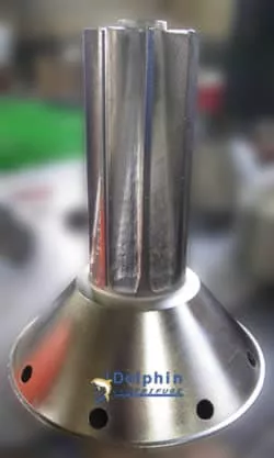
Paring Disc
aka Paring Disc Pump, Centripetal Pump
The paring disc is a static impeller device that is internal to the bowl. Though this part is inside the bowl assembly, it does not rotate. It is suspended inside the upper chamber of the bowl, which revolves around it.
The paring disc is a centripetal pump, which converts the fluid's rotational energy inside the bowl into pressure. It performs this pumping action through internal spiral vanes.
This pump is threaded on the feed tube and connects to the upper fluid discharge assemblies.
The bowl cavity housing the paring disc has a tight tolerance. This close gap means that properly assembling these components is critical because the other parts close to the paring disc are rotating.
Any contact between this stationary part and the rotating parts can cause catastrophic damage to the centrifuge.
The back-pressure maintained on the paring disc outlet is a critical operating parameter. Without adequate back-pressure, the paring disc impeller vanes will not be sufficiently immersed in the separated liquid layer, reducing pumping efficiency and potentially allowing air to enter the liquid outlet, which degrades separation. Back-pressure also helps stabilize the liquid-liquid interface within the bowl. When adjusting or troubleshooting a disc centrifuge, the back-pressure setting on each liquid outlet should always be checked and confirmed to be within the OEM-specified range for the application. A separate article on centrifuge back-pressure provides detailed guidance on this topic.
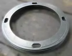
Port Liner
aka Port Wear Clips
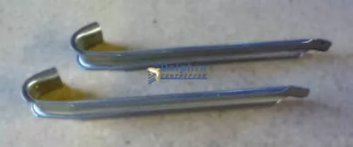
Centrifuge Bowl Port Liners
The exposure of the sludge ejection ports in the bowl body to wear is a cause for concern.
Port liners are stamped steel clips that are crimped over the exposed sludge ports. They protect the centrifuge bowl body ports from wear.
The port liner is a sacrificial part that is easily replaced at a minimal cost.
During each sludge ejection cycle, the accumulated solids are discharged through the open sludge ports at extremely high velocity due to the centrifugal force within the bowl. This high-velocity discharge of solids — particularly when the solids are abrasive materials such as sand, scale, or metal fines — rapidly erodes the edges and surfaces of the port openings. Without port liners, the bowl body itself is damaged. Since the bowl body is a precision-machined, high-strength component, repairing or replacing it due to port erosion is expensive. Port liners absorb this wear and can be replaced at a fraction of the cost. Port liners should be inspected at every bowl overhaul and replaced when any significant thinning, cracking, or deformation is observed.
Sliding Piston
aka Sliding Bowl Bottom
A brief introduction of the sliding piston is in the 'bowl liner' section above. This part is also known as the sliding bowl bottom because it slides downward at the bottom of the fluid chamber. The evacuation of the water below the piston causes the piston's downward movement.
This sliding motion of the piston opens the sludge discharge ports to the bowl's interior. The high centrifugal force exerted within the bowl pushes the accumulated solids instantly through these exposed ports. This action comprises the sludge ejection cycle of the self-cleaning centrifuge.
The sliding piston has another essential feature designed into it. A small circumferential protrusion, known as a lip, is machined onto the sliding piston's upper surface. This lip embeds into a mating part inserted into the bowl hood to form a seal. This seal keeps the bowl contents from exiting the bowl under the high centrifugal forces during regular operation.
It is essential to mention that erosion of the above-mentioned sliding-piston lip can cause the bowl contents to leak during operation. This leak can cause the separated solids to exit the bowl at a high velocity causing more wear on the lip. Therefore it is crucial to replace the nylon seal ring (explained above) to prevent wear of the sliding piston, which can be an expensive replacement.
Detailed information about Bowl Leaking and prevention is on our disc-centrifuge troubleshooting guide. The outer cylindrical surface of the sliding piston also slides within the inner bore of the bowl body. This mating surface must be clean and smooth. Any scoring, corrosion, or scale buildup on either the piston surface or the bowl bore will impede the piston's free movement, causing unreliable bowl operation. The sliding piston sealing surfaces — both the upper lip area and the outer cylinder — should be carefully inspected at each overhaul for any irregularity.
Sludge Ports
aka Sludge Ejection Ports
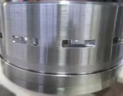
Sludge ports are rectangular slots machined on the disc centrifuge bowl body. As described in the port liner section above, these openings allow the separated solids to exit the bowl during the solids' ejection process.
Again, it is essential to protect these ports from wear by using port liners in abrasive sludge applications.
The number and size of sludge ports varies by centrifuge model and is designed to match the expected solids volume and ejection characteristics of the application. Larger ports allow higher volume sludge discharge, while smaller ports are used in applications with lower solids concentrations. The geometry of the port openings also affects how completely the sludge is discharged in each ejection cycle. Worn or eroded sludge ports may allow a partial discharge, leading to solids buildup within the bowl between cycles, which reduces separation efficiency and may cause imbalance. This is why port liner protection is so important — unprotected port erosion changes the port geometry and degrades performance over time.
Small Lock Ring
aka Paring Chamber Cover
The small lock ring is an internally threaded part that screws onto the top of the bowl hood. It secures the gravity disc to the bowl hood and houses a chamber for the heavy phase's paring disc pump.
The small lock ring serves a dual purpose: it retains the gravity disc in place on top of the bowl hood during high-speed rotation, and it creates an enclosed chamber where the heavy-phase paring disc pump operates. The heavy-phase separated liquid accumulates in this chamber before being pumped out under pressure by the paring disc. The thread engagement between the small lock ring and the bowl hood must be complete and correct — a partially engaged or cross-threaded small lock ring can unscrew during operation due to the centrifugal loading. The small lock ring also typically features a hexagonal or notched profile to allow tightening with a spanner wrench during bowl assembly. Its threads should be inspected for damage during each overhaul.
Top Disc
The top disc is a dome-shaped part positioned at the top of the disc stack. It acts as a collection cover, which funnels the separated light phase towards the center of the bowl top. The light-phase paring disc (stationary) is housed within the top disc and pumps out this clean light phase.
The separated heavy phase travels over the upper surface of the top disc and enters the small lock ring chamber. In certain respects, the top disc also acts as a barrier between the two separated phases of liquids.
Top discs can experience some wear if the process fluid carries abrasive particles.
The top disc is a precision-shaped component that must fit correctly on top of the disc stack. Its dome geometry is designed to create the correct liquid flow paths for both the light phase (directed inward to the light-phase paring disc outlet) and the heavy phase (directed outward and upward over the dome surface into the small lock ring chamber). Any deformation, warping, or scale buildup on the top disc will disrupt these flow paths and can cause cross-contamination between the separated liquid phases. Top discs should be inspected for dimensional accuracy and surface condition during each overhaul, particularly in applications where scale-forming minerals are present in the process fluid.
Unique Terms Specific to Disc Centrifuges
Specific terms are unique to the world of disc centrifuges. These terms are rare in the context of other machinery or separation equipment. In this section, we will explain some of these terms and their relevance to aspects of disc centrifuges. Understanding this vocabulary is essential for reading OEM manuals, communicating with service technicians, and diagnosing operational problems accurately.
Back-Pressure
As discussed in the 'paring disc' section above, the liquid phases are pumped out under pressure from the centrifuge bowl through a paring disc pump. Throttling the liquid outlet exerts back pressure on the exiting fluid stream. Back-pressure on the liquid outlet ensures that the paring disc impeller is immersed in the clean separated fluid. Therefore, back-pressure is only applicable to pumped fluid outlets with paring discs. Also, applying back pressure on the liquid effluent causes pressure on the fluid column within the centrifuge bowl. This pressure, in turn, has a beneficial effect on the centrifuge operation. It helps stabilize the liquid columns within the bowl, which leads to a stable interface between the liquid phases. Thus, back pressure results in better separation of the liquid phases.
Bowl Closing
This term is specific to 'self-cleaning' centrifuges. In this case, the centrifuge bowl requires water to push the operating slide and, subsequently, the sliding piston to form the seal. This event of the piston moving within the bowl to form the seal is known as bowl closing. Bowl closing must occur before process fluid is introduced into the bowl to prevent uncontrolled discharge of the process fluid through the open sludge ports. The timing and completeness of bowl closing is confirmed by monitoring the centrifuge operating water system pressure.
Bowl Opening
aka Bowl Shoot, Sludge Dump
Bowl opening is the momentary event where the sliding piston is activated to move downward, exposing the sludge ejection ports. The high centrifugal forces cause the sludge to exit the bowl in a short period. This event is often triggered by a pulse of high-pressure water in the operating water system. The bowl opening event is very brief — typically lasting only one to two seconds — but during this time, the solids accumulated in the bowl periphery are discharged entirely or partially. A 'total shoot' discharges all solids; a 'partial shoot' only discharges a fraction of the accumulated solids to reduce process liquid losses during the discharge cycle.
Break Over
aka Liquid Seal Break
Break over refers to the phenomenon where the lighter fluid (liquid/liquid separation) escapes the centrifuge bowl through the passage designed for the heavy fluid. Liquid seal breaks can occur due to multiple causes. It could be caused by the bowl not being primed before the lighter fluid flows into the bowl. In the absence of the heavy liquid, the lighter fluid exits the bowl through the passage designed for the heavier fluid. It could also happen if the gravity disc installed in the centrifuge is too large. In this case, the heavy liquid column within the bowl does not have adequate hydrostatic pressure to balance the lighter fluid pressure. The lighter fluid can push out the heavier fluid and escape through the path designed for the heavy liquid. Break over is an immediately visible problem: the separated lighter phase appears at the heavy-phase outlet, signaling incorrect gravity disc sizing or improper priming of the bowl.
Clarifier Centrifuge
aka Liquid/Solid Centrifuge
A clarifier is a disc centrifuge configured to separate one liquid phase from solids. In other words, a two-phase centrifuge. An example of a clarifier centrifuge would be one set up to separate the beer from yeast. In a clarifier configuration, there is no gravity disc since there is only one liquid outlet. The bowl is designed to maximize the volume available for solids accumulation since there is no heavy-phase liquid outlet to manage. Clarifier centrifuges are used in applications such as beer clarification, fruit juice clarification, pharmaceutical broths, starch processing, and many other liquid-solid separation applications.
Concentrator Centrifuge
aka Liquid/Liquid/Solid Centrifuge
A three-phase centrifuge is designed to separate two liquids and solids simultaneously. However, a centrifuge specifically designed for a larger proportion of the heavy liquid than the lighter liquid is a concentrator. A machining coolant centrifuge is an example of a concentrator centrifuge. It is designed to separate small amounts of tramp oil (light phase) from large volumes of coolant (water). In this configuration, the heavy phase (water/coolant) is the major outlet flow, and the light phase (oil) is the minor outlet flow. The bowl and paring disc geometry in a concentrator are optimized for the predominance of the heavy phase.
Displacement Water
In simple terms, displacement water is supplied to the centrifuge bowl before the sludge shoot cycle. The purpose of the displacement water is to replace the oil in the centrifuge bowl to reduce oil losses during the sludge discharge. Before the bowl opens, a measured volume of water is injected into the centrifuge to displace the oil from the bowl periphery (where solids accumulate). This ensures that the sludge discharge contains water and solids rather than valuable process oil mixed with solids, reducing product loss during each ejection cycle. Displacement water volume and timing are adjustable parameters in the centrifuge control system and must be optimized for the specific application.
Drain Time
During the bowl open (shoot) part of the process, the centrifuge operating water system is flooded with water in the chamber above the operating slide. The drain time is between the opening and closing sequences to allow this opening water to escape the bowl. This is to ensure that the closing operation of the bowl is accomplished smoothly. If the drain time is insufficient, residual opening water remaining in the bowl can interfere with the bowl closing operation, preventing the piston from sealing properly. This leads to incomplete bowl closure and potential process liquid leakage through the sludge ports during the next processing cycle. Drain time is a programmable parameter in the centrifuge control sequence and must be set appropriately for the centrifuge model and operating conditions.
Heavy Phase
The heavy phase refers to the liquid with the higher specific gravity in the mix of liquids separated by the centrifuge. In the case of oil and water, water is the heavy phase. This term is only applicable to the separation of two liquids. The heavy phase exits the bowl through the outer peripheral outlet path, controlled by the gravity disc, and is pumped out by the heavy-phase paring disc in the small lock ring chamber.
Light Phase
Following the above, the light phase is the liquid with the lower specific gravity in the mix of liquids being separated. In the case of oil and water, oil is the light phase. This term is also only applicable to the separation of two liquids. The light phase accumulates at the center of the bowl (closest to the axis of rotation, where centrifugal force is lowest) and exits through the inner outlet, where it is pumped out by the light-phase paring disc housed within the top disc.
Liquid-Liquid Interface
During the separation of two liquids, the liquids form concentric columns within the bowl. The liquid-liquid interface is the boundary between these liquids within the bowl. The position of this interface is controlled by the gravity disc size. Correct positioning of the interface is critical: if the interface is too far inward (toward the axis), the heavy phase may contaminate the light phase outlet. If the interface is too far outward (toward the periphery), break-over can occur. The operator must select the correct gravity disc size using the nomogram provided with the centrifuge to position the interface correctly for the specific process fluid densities and throughput.
Liquid Seal
aka Bowl Prime, Priming Liquid
The liquid seal refers to introducing the heavier phase into the centrifuge bowl before the process liquid. The centrifuge bowl's design requires the heavy phase space within the bowl to be filled before the light phase enters the bowl. This prevents the light phase from exiting the bowl through the heavy phase pathway. A liquid seal is needed only in liquid/liquid separation cases wherein the lighter phase is the predominant liquid phase. For example, when processing oil (light phase) with water present as the heavy phase minority, the bowl must first be primed with water before oil is introduced. Without this priming, the oil would immediately flow through the water outlet, and break-over would occur.
Operating Water
aka Closing Water, Opening Water
A self-cleaning centrifuge bowl ejects the separated solids by operating the sliding piston through a hydraulic mechanism. The operating water is the term for the water used for this operation. Operating water is supplied at controlled pressure and volume through the distributing cover and control paring disc to the distributing ring within the rotating bowl. The quality of the operating water matters significantly — hard water causes scale buildup in the water passages, while dirty or contaminated water can plug the passages. Most OEM specifications call for clean potable water with hardness below a specified limit. The operating water supply system should be regularly maintained to ensure reliable bowl operation.
Purifier Centrifuge
As explained above, a three-phase centrifuge separates two liquids and solids simultaneously. However, a centrifuge specifically designed for a smaller proportion of the heavy liquid than the lighter liquid is a purifier. A diesel fuel centrifuge is an example of a purifier centrifuge. It is designed to separate small amounts of water (heavy phase) from large diesel volumes. In a purifier configuration, the heavy phase is the minority outlet flow, while the light phase (oil, fuel, or other light liquid) is the major outlet flow. The bowl geometry and paring disc sizing in a purifier centrifuge are optimized for this purpose. Other examples of purifier centrifuge applications include fuel oil purification, lubricating oil purification, and hydraulic oil cleaning on marine vessels and power generation facilities.
Summary
We hope this glossary of disc centrifuge terms helps the new or existing users of industrial disc centrifuges. Though the terms referenced in this article are specific to Alfa Laval Disc Centrifuges, they are similar to those used for other disc centrifuges manufactured by GEA Westfalia.
Understanding the names, functions, and maintenance requirements of each bowl component is the foundation of competent disc centrifuge operation and service. The relationship between consumable wear parts (nylon seal ring, bowl liner, port liners) and the expensive precision components they protect (sliding piston, bowl body, bowl spindle) is a recurring theme throughout this glossary — one that has real dollar implications for any facility operating disc centrifuges.
Similarly, the terminology in the second section of this glossary — back-pressure, bowl closing, break-over, liquid seal, gravity disc selection — represents the operational vocabulary that experienced centrifuge operators use daily when tuning, troubleshooting, and operating their equipment. Fluency in this vocabulary enables faster diagnosis of operating problems and clearer communication between operators, maintenance technicians, and service engineers.
Dolphin Centrifuge maintains an extensive inventory of Alfa Laval disc centrifuge spare parts and consumables for the bowl components described in this glossary, including nylon seal rings, bowl liners, port liners, gravity discs, distributing rings, paring discs, and complete bowl rebuild kits.
Feel free to contact Dolphin Centrifuge if you have questions or need some application consulting. You can also reach us by calling (248) 522-2573.
Need genuine disc centrifuge parts or a bowl service kit?
Dolphin Centrifuge stocks nylon seal rings, sliding pistons, gravity discs, paring discs, and complete bowl service kits for all major Alfa Laval disc centrifuge models. Same-day shipping available.
Frequently Asked Questions
What is a gravity disc in a disc stack centrifuge? ⌄
The gravity disc (also called a neck ring) is a replaceable ring at the liquid discharge end of the centrifuge bowl that sets the radius of the liquid-liquid separation interface between the light and heavy phases. Selecting the correct gravity disc diameter for the process fluid density is critical to prevent liquid carryover or poor separation.
What is the difference between a paring disc and a gravity disc? ⌄
A gravity disc controls the liquid-liquid separation interface radius in three-phase (purifier) centrifuges. A paring disc is a stationary impeller disc that acts as a centripetal pump — it extracts liquid from the rotating bowl without a pump by converting rotational energy to pressure, discharging the clarified liquid against a back-pressure. They serve completely different functions.
What is meant by the "bowl speed" specification on a disc centrifuge? ⌄
Bowl speed (expressed in RPM) is the rotational speed of the disc stack centrifuge bowl. Together with the bowl radius, it determines the G-force (RCF) acting on the feed liquid. Higher bowl speed generates more centrifugal force for separating fine or closely-matched density particles and liquids. Most Alfa Laval disc centrifuges operate between 4,000 and 10,000 RPM.
What is the nylon seal ring and why is it important? ⌄
The nylon seal ring is an inexpensive consumable part that fits into a groove in the bowl hood and forms the primary seal with the sliding piston lip. It protects the expensive sliding piston from metal-to-metal wear. Replacing the nylon seal ring regularly prevents costly piston damage and bowl leaks during operation.
How many major parts are in a disc centrifuge bowl assembly? ⌄
A typical self-cleaning disc centrifuge bowl assembly contains approximately 20 major components including the bowl body, bowl hood, disc stack, distributor, sliding piston, gravity disc, paring discs, large and small lock rings, operating slide, distributing ring, distributing cone, distributing cover, control paring disc, bowl liner, port liners, nylon seal ring, bowl spindle, sludge ports, and top disc.
Need parts, service, or technical help for your disc centrifuge?
Dolphin Centrifuge stocks all major bowl components for Alfa Laval disc centrifuges and provides full bowl rebuild services at our Warren, Michigan facility. Call us for same-day parts quotes.
(248) 522-2573 • sales@dolphincentrifuge.com • Warren, MI 48089